| simulator | ||
| .gitignore | ||
| AudioThread.cpp | ||
| AudioThread.h | ||
| NoiceSynth.ino | ||
| README.md | ||
| SharedState.cpp | ||
| SharedState.h | ||
| simulator_screenshot.jpg | ||
| synth_engine.cpp | ||
| synth_engine.h | ||
| UIThread.cpp | ||
| UIThread.h | ||
NoiceSynth
NoiceSynth is a digital grid-based modular synthesizer engine designed for the Raspberry Pi Pico (RP2040). It allows you to construct complex sound patches by placing and connecting modules (oscillators, filters, envelopes, etc.) on a grid.
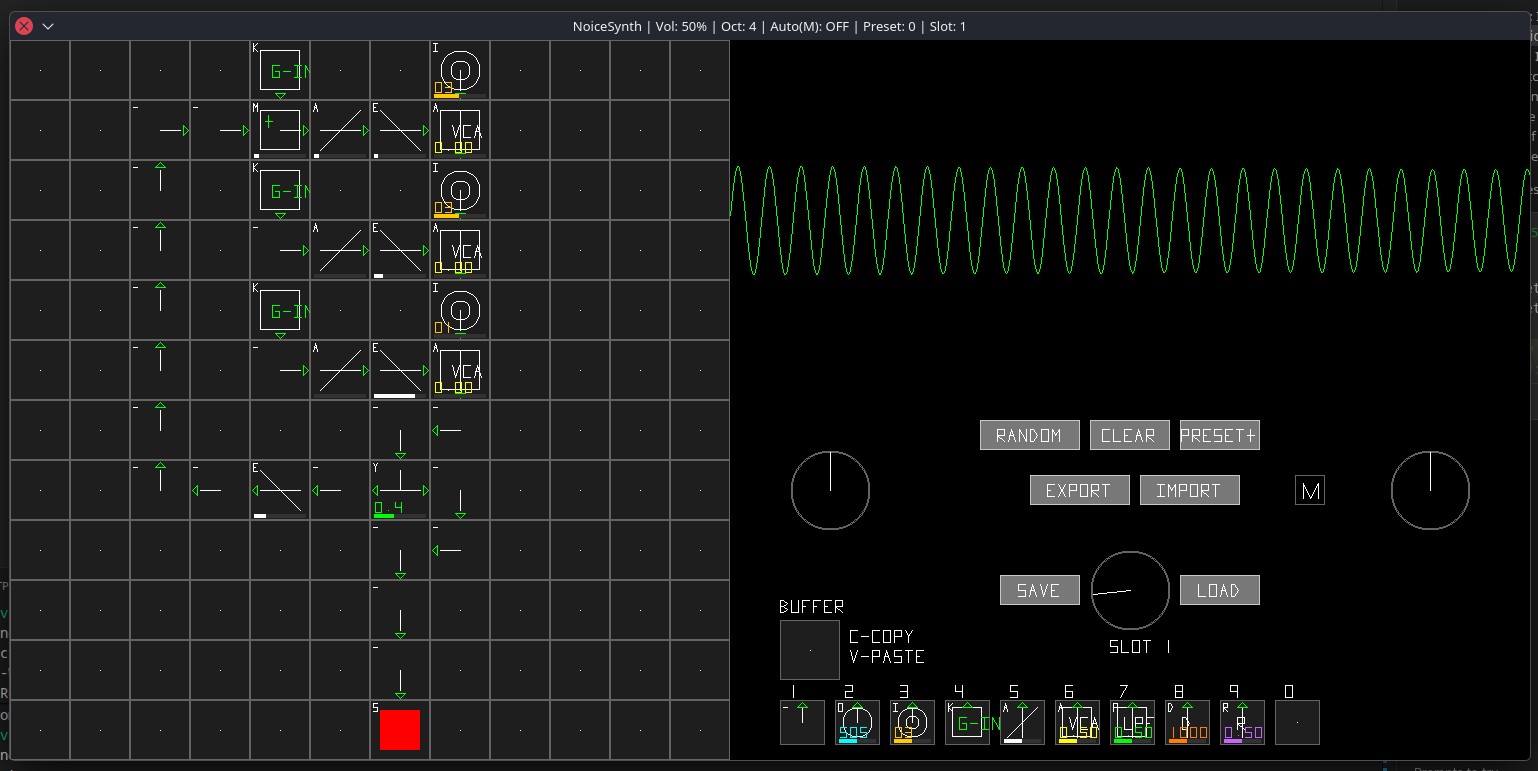
Simulator
A desktop simulator is included to allow you to design patches and test the synthesis engine without hardware. It can also transfer the patches between the device and the simulator, acting as a patch editor.
Included are 8 demo patches, plus a few built-in presets that mimic the DX7 FM synth.
Features
- Grid-Based Modular Synthesis: Build patches by placing modules on a 12x12 grid.
- Compact & Portable: Designed to be powered by a LiPo battery and fit into a small tin.
- High-Quality Audio: Uses an I2S audio module for clean, low-noise sound output.
- MIDI Connectivity: Standard 3.5mm TRS-A MIDI input for control with external keyboards and sequencers.
- Expressive Controls: Features a rotary encoder for navigation and a potentiometer for volume control.
- Visual Feedback: A crisp 128x64 OLED display shows synth parameters and status.
Hardware Requirements
| Component | Description |
|---|---|
| MCU | Raspberry Pi Pico or Pico W (RP2040) |
| Audio Output | I2S DAC Amplifier (e.g., MAX98357A or PCM5102A) with a 3.5mm headphone jack. |
| Display | 0.96" SSD1306 128x64 I2C OLED Display. |
| Controls | 1x Rotary Encoder with push-button, 1x 10kΩ Potentiometer. |
| MIDI Input | 1x 3.5mm TRS (Stereo) Jack. |
| Power | 3.7V LiPo Battery and a 5V booster/charger board (e.g., Adafruit PowerBoost). |
| MIDI Circuit Parts | 6N138 or 6N137 Optocoupler, 1N4148 Diode, various resistors (see diagram). |
Powering Your Synth
You can power the synth either from a portable LiPo battery or directly from USB.
Battery Operation (Portable)
To make the synth truly portable, use a LiPo battery and a 5V booster/charger board. This provides stable power to all components.
LIPO BATTERY WARNING: LiPo batteries are powerful but require careful handling.
- Never use a LiPo battery without a dedicated protection and charging circuit like the PowerBoost.
- Do not puncture, bend, or short-circuit a LiPo battery.
- Connect the LiPo battery to the JST connector on the PowerBoost board.
- Connect the PowerBoost's 5V output to the Pico's VBUS pin (Pin 40). This powers the Pico.
- Connect the PowerBoost's 5V output to the VCC/VIN pin of your I2S Audio Module.
- Connect the PowerBoost's GND to one of the Pico's GND pins. This creates a common ground.
USB Operation
If you don't need battery power, you can run the synth from a USB source (like a computer or wall adapter). The wiring is simpler.
There are two ways to power the components:
Option 1 (Simplest): Power everything from 3.3V The PCM5102A DAC chip runs natively on 3.3V. This is the easiest and safest wiring method for USB operation.
- Power the Pico by connecting its micro-USB port to a USB power source.
- Connect the Pico's 3V3(OUT) pin (Pin 36) to the VCC/VIN pins of all components: the I2S Module, OLED, Rotary Encoder, Potentiometer, and MIDI circuit.
- Ensure all components share a common ground with one of the Pico's GND pins.
Option 2: Power I2S Module from 5V (with protection) If you prefer to give the audio module a separate 5V supply from USB. For good measure, adding a Schottky diode (e.g., 1N5817) is recommended to protect against any potential reverse voltage.
- Power the Pico via its micro-USB port.
- Connect the Pico's VBUS pin (Pin 40) to the anode (+) of a Schottky diode. Connect the cathode (-) of the diode to the VCC/VIN pin of your I2S Audio Module.
- Connect the Pico's 3V3(OUT) pin (Pin 36) to power the OLED, Encoder, Potentiometer, and MIDI circuit.
- Ensure all components share a common ground.
Wiring & Connections
Establish a common ground by connecting the ground from your PowerBoost board to the Pico, and then to all other components' GND pins.
| Component | Pico Pin | Description |
|---|---|---|
| I2S Audio Module | ||
| VCC | 3.3V or 5V Source (see Power section) | Power for the amplifier |
| GND | Common GND | Ground |
| DIN (Data) | GP11 (Pin 15) | I2S Data Out |
| BCLK (Bit Clock) | GP9 (Pin 12) | I2S Bit Clock |
| LRCK (Word Clock) | GP10 (Pin 14) | I2S Left/Right Clock |
| SCK (System Clock) | GND | PCM5102 Only: Connect to GND for internal PLL |
| SSD1306 OLED | ||
| VCC | 3V3 (OUT) (Pin 36) | 3.3V Power |
| GND | Common GND | Ground |
| SDA | GP4 (Pin 6) | I2C Data |
| SCL | GP5 (Pin 7) | I2C Clock |
| Rotary Encoder | ||
| + (VCC) | 3V3 (OUT) (Pin 36) | 3.3V Power |
| GND | Common GND | Ground |
| CLK | GP12 (Pin 16) | Encoder Clock |
| DT | GP13 (Pin 17) | Encoder Data |
| SW | GP14 (Pin 19) | Encoder Switch |
| Volume Pot | ||
| VCC | 3V3 (OUT) (Pin 36) | 3.3V Power |
| GND | Common GND | Ground |
| Wiper (Output) | GP26 (Pin 31) | ADC0 for volume reading |
| MIDI IN | ||
| (Circuit Output) | GP1 (Pin 2) | UART0 RX for MIDI Data In |
MIDI IN Circuit (TRS Jack)
MIDI requires an opto-isolated input to protect the Pico from electrical faults. We will use a Type A TRS MIDI wiring standard, which is the most common.
- TRS Tip: Connects to MIDI Pin 5 (Current Source)
- TRS Ring: Connects to MIDI Pin 4 (Current Sink)
- TRS Sleeve: Connects to MIDI Pin 2 (Ground/Shield)
Here is a schematic for the input circuit:
TRS JACK
  TIP ---- 220Ω ----+----|>|---- (Pin 6 of 6N138)
(MIDI 5)            |  (Diode)
                    |
 RING --- 220Ω -----+----------- (Pin 5 of 6N138)
(MIDI 4)

6N138 OPTOCOUPLER
  Pin 8 (VCC) ----> 3.3V (from Pico)
  Pin 7 (VB)  ----> GND
  Pin 6 (E)   --+-> 10kΩ Pull-up Resistor -> 3.3V
                |
                +-> To Pico GP1 (UART RX)
  Pin 5 (GND) ----> GND
This circuit correctly isolates the incoming MIDI signal and inverts it for the Pico's UART receiver.
Software Setup
-
Install RP2040 Board Core:
- In the Arduino IDE, go to Preferences and add this URL to "Additional Boards Manager URLs":
https://github.com/earlephilhower/arduino-pico/releases/download/global/package_rp2040_index.json - Go to Tools > Board > Boards Manager, search for "pico", and install Raspberry Pi Pico/RP2040.
- Select Raspberry Pi Pico from the board menu.
- In the Arduino IDE, go to Preferences and add this URL to "Additional Boards Manager URLs":
-
Install Libraries:
- Install the following from the Arduino Library Manager:
Adafruit GFX LibraryAdafruit SSD1306- An I2S Audio Library for the Pico (e.g.,
I2Sby Earle F. Philhower, III, which is often included with the core).
- Install the following from the Arduino Library Manager:
-
Upload Code:
- Once everything is wired, you can upload your synthesizer code to the Pico.
Controls & Usage
The specific function of the controls will depend on your code, but here is a common layout:
- Rotary Encoder (Turn): Navigate menus, change synth parameters (e.g., waveform, filter cutoff), or select notes.
- Rotary Encoder (Press): Enter/exit edit mode for a parameter, or trigger an action.
- Volume Potentiometer: Controls the final output volume before it goes to the headphone jack.
Happy building, and enjoy your new tiny synth!