|
1234567891011121314151617181920212223242526272829303132333435363738394041424344454647484950515253545556575859606162636465666768697071727374757677787980818283848586878889909192939495969798 |
- # Video Terminal Hardware
- Build instructions for the video-terminal-revival project.
-
- ## Bill of Materials
- - ESP32 development board
- - USB cable (for development)
- - 5V power source (may be a 12V step down converter)
- - Display with composite input (TV, monitor)
- - RCA cable
- - RCA socket
- - resistors: 2x 1k ohm
- - LK201 keyboard
- - RJ-11 socket
- - MAX2323 TTL-RS232 conversion board
- - 12V power source + connector socket
-
- ## Build
- ### Display
- Connect the TV via the RCA cable to the RCA socket, then through a voltage divider into the ESP32:
-
- ```
- ESP32 TV
- -------+
- GND |-+------------------ Composite (-)
- | | ____ 1k ohm
- | +-|____|-+ (RCA socket)
- | ____ |
- pin25 |---|____|-+--------- Composite (+)
- -------+ 1k ohm
- ```
-
- ### Keyboard
- Connect the keyboard into the RJ-11 socket, hook that into a 12V power source and the RS-232 converter, then to the ESP32's serial port:
-
- ```
- [GND][12V]
- [1] | | [2]
- | | | |
- ------------------- MAX2323 ESP32
- | " " " " | +-----------+ +--------
- | E G 1 L | [1]--| <- - |-----------| GND
- | S N 2 K | [2]--| -> + |--[5V] |
- | P D V -> | x-| + <- |-----------| pin17
- | -> E | [GND]--| - -> |-----------| pin16
- | L S | +-----------+ +--------
- | K P |
- -- --
- | |
- -- --
- | |
- -------
-
- Looking into the RJ-11 Socket
- on the ESP32-side (i.e. DEC)
-
- ```
-
- 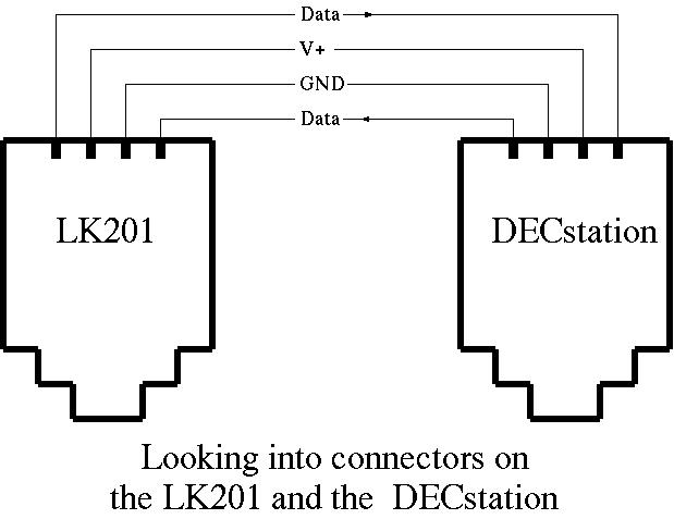
- Source: [LK201 Interface](http://www.netbsd.org/docs/Hardware/Machines/DEC/lk201.html)
-
- 
-
- ### TTY
- This part depends on what serial port you are connecting to. Most SBCs (e.g. Orange Pi) provide pins for TTL serial port, alternatively you can use a USB-Serial dongle. Either way you can connect the ESP32 directly to this:
-
- ```
- ESP32 Serial port
- -------+ +---
- GND |--------------|GND
- pin18 |--------------|TX
- pin19 |--------------|RX
- -------+ +---
- ```
-
- ### CPU
- The ESP32 should now be connected to both the keyboard and the display, as well as the "mainframe" (serial port) it will be talking to.
-
- For development (or at least the first flashing), all that remains is to connect it over USB to a computer with the Arduino IDE.
-
- For production use, connect it to a 5V power source.
-
- 
-
- ### Finishing
- For bonus points, place everything on a PCB, solder it, put it into a cool enclosure and go impress your friends!
-
- Following is a gallery of one possible solution.
-
- #### TV (original)
- 
- 
-
- #### TV (modified)
- 
-
- #### TV + Keyboard
- 
-
|