3.0 KiB
Video Terminal Hardware
Build instructions for the video-terminal-revival project.
Bill of Materials
- ESP32 development board
- USB cable (for development)
- 5V power source (may be a 12V step down converter)
- Display with composite input (TV, monitor)
- RCA cable
- RCA socket
- resistors: 2x 1k ohm
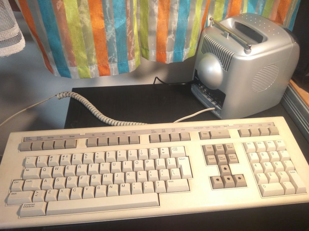
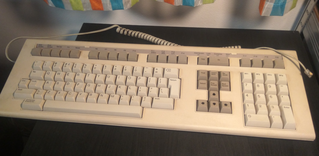
- LK201 keyboard
- RJ-11 socket
- MAX2323 TTL-RS232 conversion board
- 12V power source + connector socket
Build
Display
Connect the TV via the RCA cable to the RCA socket, then through a voltage divider into the ESP32:
ESP32                             TV
-------+
   GND |-+------------------ Composite (-)
       | |  ____ 1k ohm
       | +-|____|-+           (RCA socket)
       |    ____  |
 pin25 |---|____|-+--------- Composite (+)
-------+         1k ohm
Keyboard
Connect the keyboard into the RJ-11 socket, hook that into a 12V power source and the RS-232 converter, then to the ESP32’s serial port:
      [GND][12V]
  [1]   |    |   [2]
   |    |    |    |
  -------------------               MAX2323                ESP32
 | "    "    "    "  |           +-----------+           +--------
 | E    G    1    L  |      [1]--| <-      - |-----------| GND
 | S    N    2    K  |      [2]--| ->      + |--[5V]     |
 | P    D    V    -> |         x-| +      <- |-----------| pin17
 | ->             E  |    [GND]--| -      -> |-----------| pin16
 | L              S  |           +-----------+           +--------
 | K              P  |
  --               --
    |             |
     --         --
       |       |
        -------

Looking into the RJ-11 Socket
on the ESP32-side (i.e. DEC)
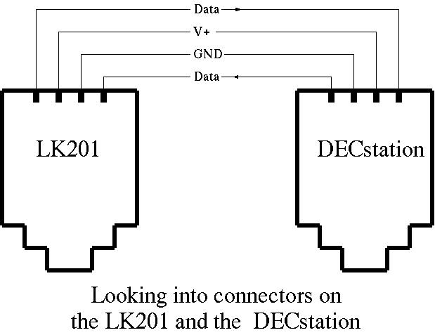 Source: LK201 Interface
TTY
This part depends on what serial port you are connecting to. Most SBCs (e.g. Orange Pi) provide pins for TTL serial port, alternatively you can use a USB-Serial dongle. Either way you can connect the ESP32 directly to this:
ESP32               Serial port
-------+              +---
   GND |--------------|GND
 pin18 |--------------|TX
 pin19 |--------------|RX
-------+              +---
CPU
The ESP32 should now be connected to both the keyboard and the display, as well as the “mainframe” (serial port) it will be talking to.
For development (or at least the first flashing), all that remains is to connect it over USB to a computer with the Arduino IDE.
For production use, connect it to a 5V power source.
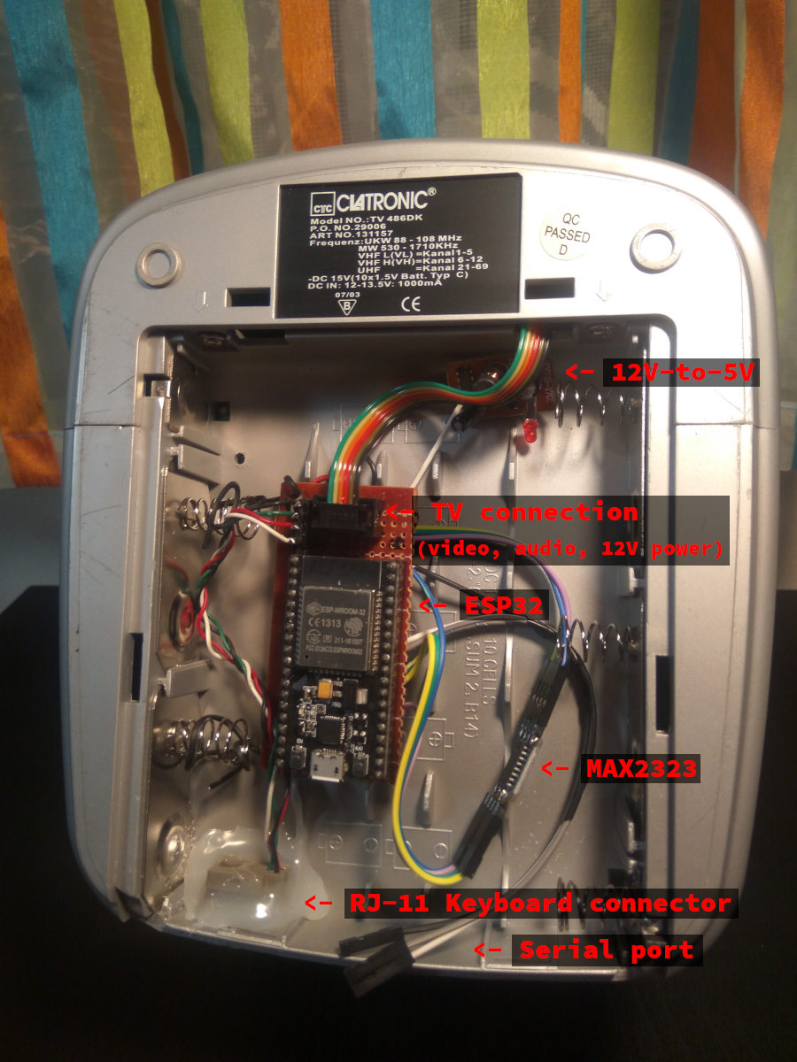
Finishing
For bonus points, place everything on a PCB, solder it, put it into a cool enclosure and go impress your friends!
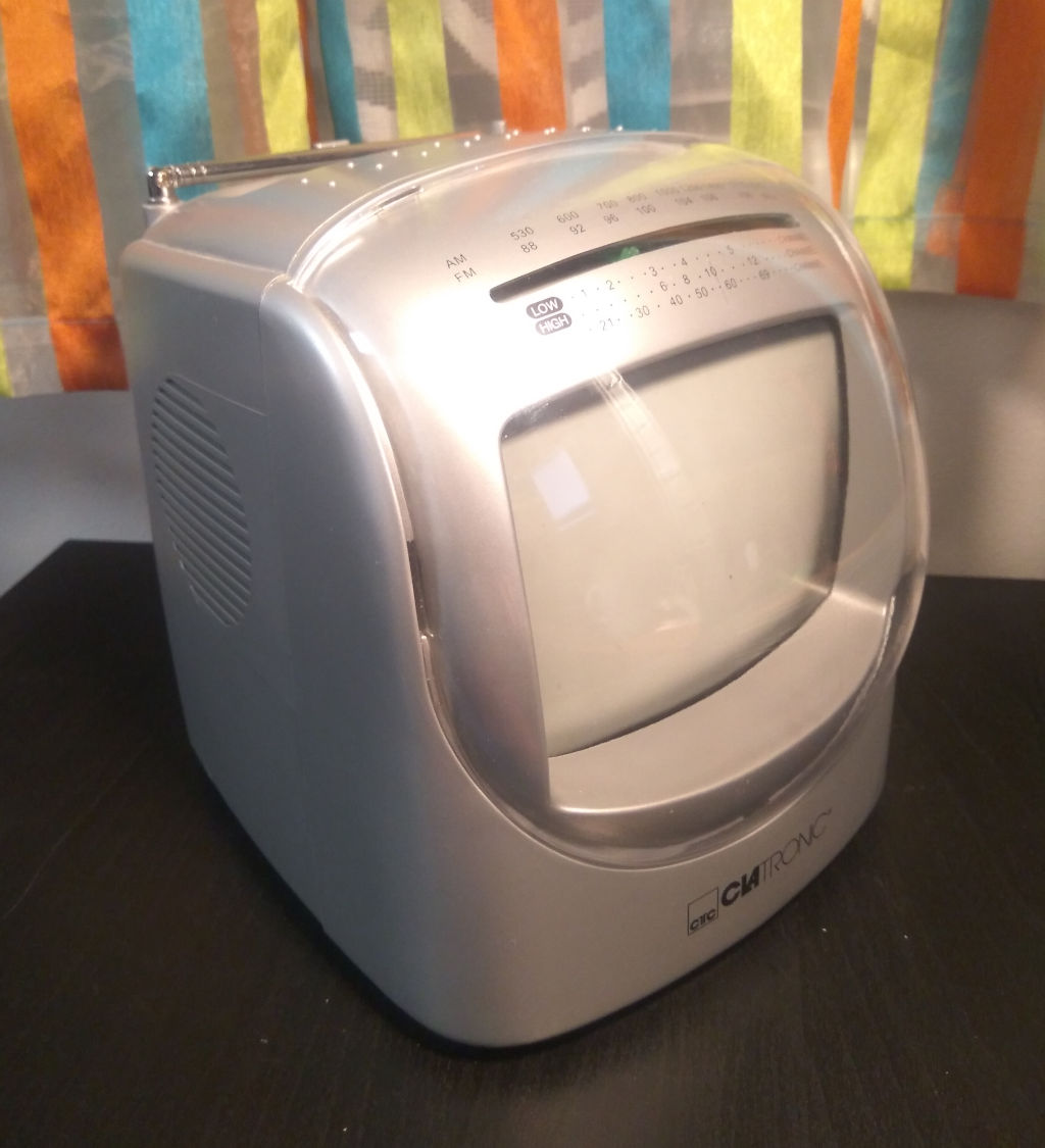
Following is a gallery of one possible solution.
TV (original)
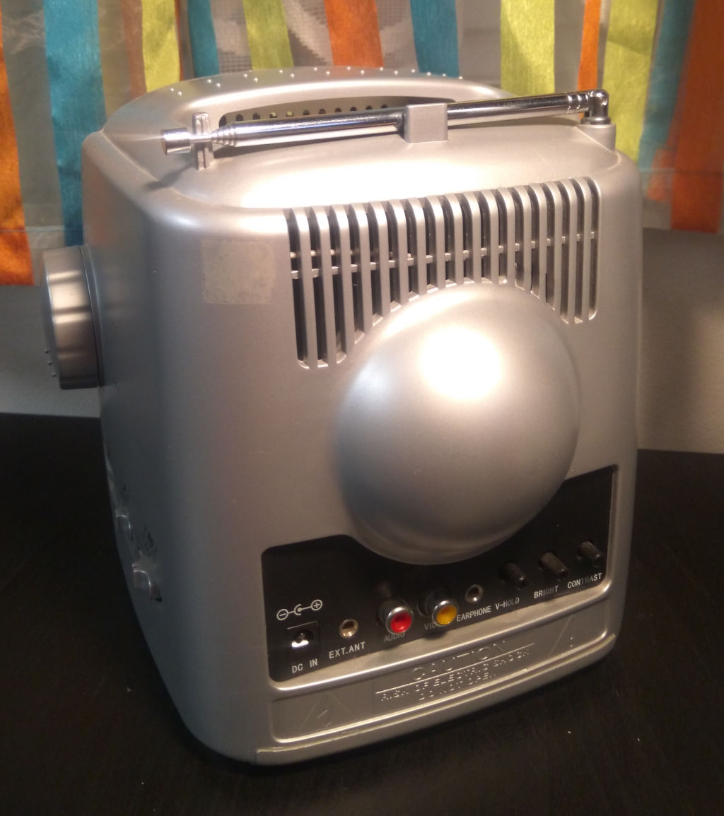
TV (modified)
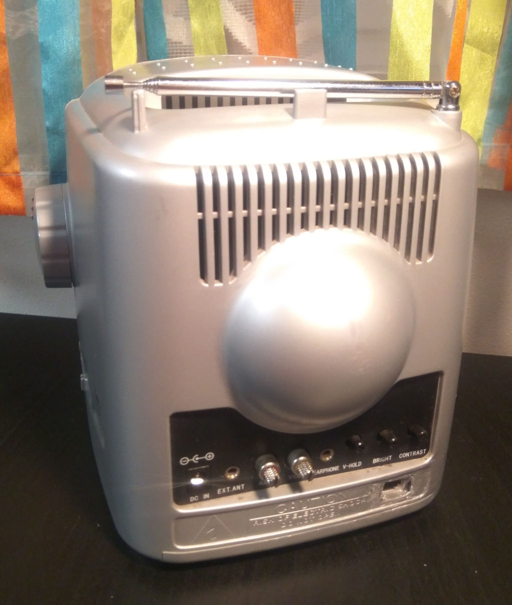
TV + Keyboard